How to Connect LED Strip Lights Together: 3 Safe Ways That Work
To connect LED strip lights together safely, first match the voltage, strip width, pad layout, and polarity. Then choose one of three methods: solderless connectors for quick indoor joins, soldered wires for permanent connections, or short wire bridges for corners, gaps, and custom layouts.
This guide is for connecting LED strip sections after cutting, extending a run, repairing a weak join, or joining strips around furniture, cabinets, shelves, corners, and longer layouts without flicker, dimming, or reversed wiring.
Quick Answer
The easiest way to connect LED strip lights is to use a compatible solderless connector. For stronger permanent joins, solder the wires directly to the copper pads. For corners, gaps, shelves, and hidden runs, use short wire bridges so the strip is not bent or stressed.
- Use solderless connectors for quick strip-to-strip joins
- Use soldering for permanent or high-reliability connections
- Use short wire bridges for corners, gaps, and custom layouts
- Match voltage, strip width, pad layout, and polarity before connecting
- Test the full strip before peeling the backing or mounting it permanently
Table of Contents:
- Quick Answer
- Before You Connect LED Strip Lights
- Which Connection Method Should You Choose?
- How to Connect LED Strip Lights Without Soldering
- How to Solder LED Strip Connections
- How to Join LED Strip Sections Across Gaps and Corners
- When LED Strip Connections Need Power Injection
- Why Your LED Strip Connection Is Not Working
- FAQ
- Key Takeaways
- Sharing This Guide
Before You Connect LED Strip Lights
Before you connect LED strip lights together, check four things: voltage, strip width, pad layout, and polarity. Most low-voltage strips run on 12V or 24V DC power, and each cut point has copper pads where the electrical connection is made.
Single-color LED strips usually have two pads marked positive and negative. RGB strips often have four pads for red, green, blue, and a common connection. RGBW, tunable white, and addressable strips may use different layouts, so do not assume every connector fits every strip.
Only connect strips with the same voltage rating and compatible copper pad layout. Joining a 12V strip to a 24V strip can damage the strip, cause overheating, or shorten its lifespan very quickly. If you are still deciding which system to build around, this guide to LED strip voltage — 5V, 12V and 24V compared explains the practical differences before you start wiring.
Polarity matters just as much as voltage. If positive and negative are reversed, the strip usually will not light, and some controllers or smart modules may be damaged. Check the markings on both strip ends before locking a connector or soldering a wire.
If you are starting from scratch instead of repairing an existing strip, using a complete RGB LED strip kit with app control can be simpler than mixing random strip sections, controllers, and power supplies. Just make sure any future extensions use compatible voltage, width, and pin layout.
Which Connection Method Should You Choose?
The best way to join LED strip lights depends on whether the connection needs to be quick, permanent, hidden, or strong enough for a long run. The three main safe connection methods are solderless connectors, soldered wire joints, and short wire bridges. Power injection is an extra step for longer runs that start to dim.
For a quick indoor extension: use a solderless connector. It is fast, beginner-friendly, and does not require tools.
For a permanent installation: use a soldered wire joint. It gives stronger contact and is less likely to loosen over time.
For corners, gaps, shelves, or cabinets: use a short wire bridge. It lets the strip turn or jump a gap without bending the tape.
For long runs with dimming at the far end: use power injection. It adds extra power points so brightness stays more even.
If the strip is easy to reach and the installation is temporary, a connector is usually enough. If the strip will be hidden inside a cabinet, ceiling recess, display shelf, or channel, soldering or a protected wire bridge is usually worth the extra effort.
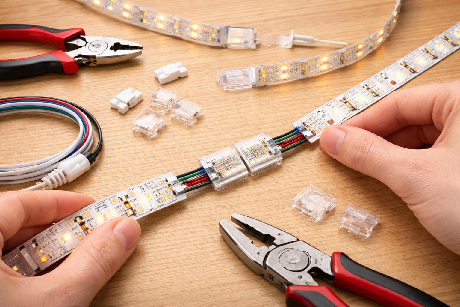
How to Connect LED Strip Lights Without Soldering
For most simple home projects, solderless connectors are the easiest way to connect LED strip lights together. They work well for quick extensions, strip-to-strip joins, and beginner-friendly indoor installs, as long as the connector matches the strip width and pin layout.
For example, many RGB strips use 10mm 4-pin layouts, so a set of compatible 10mm 4-pin solderless LED strip connectors can be useful when you want a quick join without a soldering iron. Always confirm your own strip type before buying, because single-color, RGB, RGBW, and addressable strips do not all use the same connector.
Start by cutting only at the marked cut points so the copper pads remain fully exposed. If the strip has adhesive residue, dust, coating, or oxidation on the pads, clean them gently before inserting the strip into the connector. Dirty copper pads are one of the most common reasons solderless connectors flicker or fail.
Open the connector cover, slide the strip in until the copper pads sit directly under the metal contacts, and close the latch firmly. The strip should sit flat without twisting or forcing. After locking the connector, give the strip a gentle pull to confirm it is seated properly.
Before mounting anything permanently, power the section and check for full, even illumination. If one section does not light, flickers, or shows the wrong color, disconnect power and check pad alignment, polarity, pin order, and contact pressure before blaming the strip itself.
Do not force a strip into a connector that does not fit. A connector that is too narrow, too wide, or built for the wrong pin layout can bend contacts, damage copper pads, or create intermittent flicker.
How to Solder LED Strip Connections
Soldering creates the strongest and most dependable LED strip connection. It is usually the better choice for permanent installations, long-term use, hidden layouts, areas with vibration, or custom wire bridges between sections.
You will need a temperature-controlled soldering iron set to about 315–350°C, lead-free solder, flux, wire strippers, small cutters, and a stable surface. A helping-hands tool or compact clamp also makes the job easier because it keeps the flexible strip from moving while you work.
Apply a small amount of flux to each copper pad, then tin the pads with a thin layer of solder. Strip about 3–4 millimeters of insulation from the wire ends and tin those as well. Pre-tinning both surfaces helps the final joint form faster and reduces the time the strip is exposed to heat.
Place the tinned wire onto the tinned pad and touch it briefly with the iron until the solder flows together. Remove the heat as soon as the joint forms. A clean joint should look smooth and secure, not dull, cracked, or blobbed across nearby pads.
Wire gauge matters too. Short bridges on standard strips often work with 22 AWG wire, while brighter strips, longer gaps, or higher current runs may need 20 AWG or 18 AWG to reduce resistance and voltage drop.
Never hold the soldering iron on the copper pad longer than necessary. Too much heat can lift pads, damage the flexible board, or weaken nearby LEDs, especially on narrow or lower-quality tape.
How to Join LED Strip Sections Across Gaps and Corners
Many LED strip projects need more than a straight strip-to-strip join. You may need to cross a shelf gap, turn around a cabinet corner, hide wiring behind trim, or avoid placing the strip where it would be visible. In those cases, a short wire bridge is usually cleaner than bending the LED strip itself.
For a wire bridge, connect positive to positive and negative to negative across the gap. On RGB strips, keep the red, green, blue, and common pins in the same order from one section to the next. Labeling the wires before closing a channel or cover can save a lot of troubleshooting later.
For 90-degree turns, L-shaped connectors can save time when the corner is clean and the strips line up perfectly. For angles that are not exactly 90 degrees, or for corners where the strip would need to bend sharply, short jumper wires are usually safer and neater.
Try to plan corners around the strip’s marked cutting points. That gives you usable copper pads exactly where the join needs to happen and avoids awkward cuts. If you are not sure where to cut, review this guide on how to cut LED strip lights before making permanent changes.
After making the connection, protect exposed joints with heat-shrink tubing or carefully applied electrical tape. Heat-shrink usually looks cleaner and adds better strain relief. Secure nearby wires with clips or anchors so the solder joint is not carrying the full pull of the cable.
Outdoor, bathroom, kitchen, and damp-area projects need extra care because connectors and exposed joints can become weak points. If moisture is part of the installation, this guide to outdoor and waterproof LED strip lights explains what to consider before relying on standard indoor connectors.
When LED Strip Connections Need Power Injection
Long LED strip runs often need more than one power feed. Power injection adds extra positive and negative connections farther down the strip so brightness stays more even from beginning to end.
Voltage drop becomes more noticeable as strip length increases because the copper traces on the strip have limited capacity. Once the run gets long enough, some energy is lost along the way, and the far end can look dimmer than the beginning.
This can appear after roughly 5 meters on many 12V strips, while 24V strips often handle longer runs before the problem becomes obvious. High-brightness strips can show voltage drop sooner because they draw more current.
If brightness is your main concern, this LED strip light brightness guide explains how strip output, length, voltage, and layout affect how even the light looks in real installations.
Even when the method is correct, LED strip connections can fail because of reversed polarity, poor pad contact, weak solder joints, crossed RGB channels, or voltage drop. Use the symptoms to narrow the problem before replacing parts.
A practical approach is to add positive and negative injection wires at suitable intervals based on strip voltage, wattage, and total length. Whenever possible, run those injection wires back to the main power supply instead of feeding every section from the previous one. A parallel-style wiring plan is usually easier to troubleshoot and more consistent than feeding very long strips in series.
For larger low-voltage lighting layouts, make sure the power supply, wire gauge, connections, and installation method are appropriate for the total load. The National Electrical Code is a useful reference point for broader electrical safety principles, but local rules and product instructions should always be followed.
Why Your LED Strip Connection Is Not Working
Even when the method is correct, LED strip connections can fail because of reversed polarity, poor pad contact, weak solder joints, crossed RGB channels, or voltage drop. Use the symptoms to narrow the problem before replacing parts.
If the problem appears after a new installation, it is also worth checking these common LED wiring mistakes, especially before replacing connectors, strips, or power supplies.
No light after the join: this is usually caused by reversed polarity or no pad contact. Check the positive and negative markings, then reseat the connector.
Flicker around the connection: this often points to a loose connector, dirty pads, or a cold solder joint. Clean the pads, inspect contact pressure, and reflow weak solder if needed.
Far end looks dimmer: this is usually voltage drop. Measure voltage along the run and consider power injection if the drop becomes noticeable.
RGB section shows wrong color: the color channels are probably crossed. Confirm that red, green, blue, and common pins stay in the same order across the connection.
If a strip flickers even after the connection has been checked, the problem may be broader than the join itself. This guide on why LED lights flicker and how to fix it covers dimmers, power supplies, overloaded circuits, and other common causes.
If an RGB or RGBIC strip behaves differently after a join, check whether the strip is analog RGB or addressable RGBIC. They do not use the same wiring logic. This comparison of RGB vs RGBIC LED strips explains the difference before you mix controllers, connectors, or strip sections.
FAQ
Can You Connect LED Strip Lights Without Soldering?
Yes. You can use solderless LED strip connectors if the connector matches the strip width, voltage type, and pin layout. They are best for quick indoor joins, simple extensions, and beginner projects. For permanent or hidden installations, soldering is usually more dependable.
Can You Reconnect LED Strip Lights After Cutting Them?
Many standard LED strips can be reconnected after cutting if you cut at the marked points and the copper pads remain usable. However, not every smart strip is designed to be reconnected after cutting. If you prefer a clean plug-and-play system and do not need to reconnect cut sections, a plug-and-play smart lightstrip may be convenient, but always check the manufacturer’s cutting and reconnection rules before modifying it.
Can You Connect Two Different LED Strip Brands Together?
Sometimes, but only if the voltage, strip type, width, pad layout, polarity, controller type, and power requirements are compatible. Mixing brands without checking these details can cause flicker, wrong colors, dimming, or damage.
Why Does My LED Strip Stop Working After the Connector?
The most common causes are reversed polarity, copper pads not touching the connector contacts, a dirty or damaged pad, a loose latch, or a broken solder joint. Disconnect power, realign the pads, clean the contact area, and test the section before mounting it again.
Key Takeaways
Connecting LED strip lights successfully comes down to a few basics: match the voltage, use the right connector type, line up the copper pads correctly, and keep polarity consistent across every section.
Solderless connectors are usually the fastest option for simple indoor jobs, while soldering is stronger for permanent connections. Short wire bridges are best for corners, gaps, shelves, cabinets, and layouts where the strip should not be bent.
If the strip flickers, dims, shows the wrong color, or stops after the join, check polarity, pad contact, solder quality, wire gauge, and voltage drop before replacing the strip.
Sharing This Guide
If you found this guide useful, save it for later or share it with someone planning an LED strip project. It is especially helpful for beginners, homeowners, and DIY users connecting strip sections, corners, shelves, or longer runs.
Share using the links below.
Interested in learning more? Browse all related articles in our LED strips category.